Friday, February 18, 2011

Progress, Real Progress

More progress yesterday.  I installed the steering rack which is the device that connects the steering wheel with the front wheel spindles.  With that, I officially have steering.

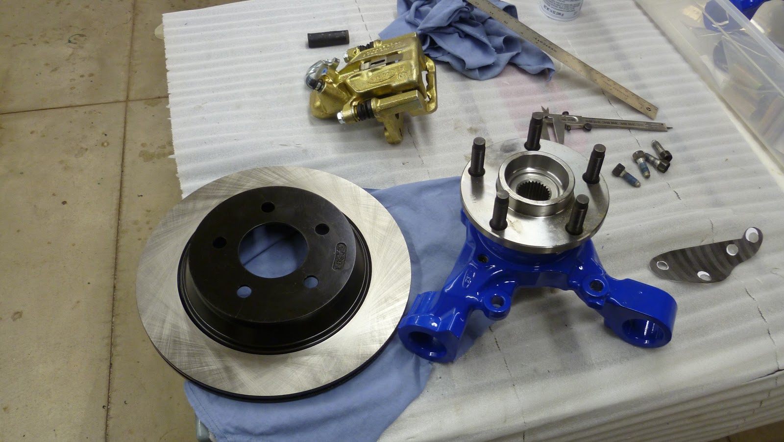
I also finished the rear suspension and installed the axles.  Here is one of the axles about to go into the rear spindle.  There is one of these for each side of the car so that they can operate independently.

Here is the axle and spindle installed.

Basically, all four corners of the car are done and if I had my wheels/tires, I'd be able to have the boys push me around the driveway like a go-kart (a 500 lb. go-kart, that is).

So, here I am, back at the computer trying to figure out what's next.  First, I have to step back for a few minutes and enjoy my accomplishments so far.  Okay, enough of that, now what's next?

As I've probably said before, the aluminum panels that make up the engine compartment will be powder coated pearl black.  Since there is some lead time involved, I want to get those panels to the painter asap!  The problem is that I'm still designing them which means I have to make decisions about other things I'm not ready to decide yet.  For example, some of the panels will surround the radiator. But I don't have a radiator yet and I'm not sure what size it will be or exactly where I want to put it.  Some of the panels depend on how the body will sit on the car, but I don't want to temporarily mount the body if I don't have to.  Anyway, I'll have some design decisions to make, aluminum to buy (Metal Supermarket again), and I'll have to make a device that helps me make long, straight bends in the panels after I cut them out.  More on all that in future posts.

When the panels are at the painter, I'll probably work on a hydraulic clutch system I've been designing and finish the other pedal modifications.

Here's an interesting side note.  Sometime in the next few months, look for me in your copy of Kit Car magazine.  Before Christmas, I had another car builder come over to use my shop for some work he was doing on his car.  We took pictures of each step along the way.  Well, he wrote an article about the modifications he was making and submitted it to the magazine.  Who knows when it will be published, but supposedly, there a picture of me cutting out some of his parts.  I'll post if here when I get it.

Wednesday, February 16, 2011

Go, Greased Lightnin', You're Burnin' Up the Quarter Mile

One evening, Laurie and I were watching the History Channel and the show Modern Marvels came on.  I laughed when I saw the show was about "grease" (not the musical).

A month later, I'm in my garage and the front suspension just isn't working smoothly.  As I researched possible causes, one probable problem was using the wrong grease!  I went back to the show and ordered the same type of grease used on the catapults of aircraft carriers.  Unfortunately, it only comes in 55 gallon drums so if anyone needs to lube their car (or anything else), come see me.  Anyway, it did the trick and now the suspension moves very smoothly.  (Note:  I was told the grease won't help launch my car from zero to 165 mph in 2 seconds like a real catapult does!).

With the suspension set, I spent today installing the front brakes and tightening the bolts (hopefully for the final time).


It took me about a day to get one side done.  I think I had to take it apart about 3 times to fix things and adjust pieces.  The other side took 1-1/2 hours.  The power of learning!

Now I'm finishing the rear suspension which will be pretty much the same exercise.  Here's a couple pictures of the differential that Ben and I installed the other day along with the rear control arms.  In case you were wondering, yes, this part of the project will use some of that special grease too!


While I was waiting for the grease delivery, I did a few other things to move the project along.  For one, I bought new bushings for the rear spindles and they had to be installed.  Here is a picture of one.  Notice that there are ridged ends on both sides and it has to be slid through a hole that will hold the narrower, middle section.

I put some of the old, standard grease on it and tried whacking it with a hammer.  That didn't work at all.  Since it's made of hard rubber, all the hammer did was bounce and it was almost like the bushing was laughing at me.  "Ha, Ha, I'm not going in that small hole".  I needed a smarter idea so I made my own press using a long threaded rod, some nuts, washers and spacers.

Here is part of the setup.

The idea is that I'll turn the two nuts against each other and slowly draw the bushing into the hole.  Here's a picture of the whole setup in action.

The bushing contorted and screamed as I slowly compressed it, but it couldn't overcome the pressure and finally had to go through the hole.  Look who's laughing now!

The other thing I did was to layout the sheet metal for the passenger foot area.  I used poster board to make a full size template that I'll copy onto sheets of aluminum and then rivet the pieces together.


Looks like I'll be making another trip to Metal Supermarket.  Aisle 6, I believe.

Wednesday, February 9, 2011

Brake Bracket Bingo, Part 2

It's hard to believe it has been a week since my last update.  What am I doing all day?  Anyway, in my previous post, I was preparing to make brackets to mount the rear brake calipers. 

The first thing I had to do was find some 1/4" thick steel plate for the brackets.  Where does one go for such a thing?  The supermarket, of course!  Okay, not just any supermarket, but the Metal Supermarket.  It's just like a regular market, only with metal, lots of metal.


I found what I was looking for on aisle 4, between the cereal and the canned tomatoes.  At the checkout, I showed the guy my template with the graceful curves and tight radii, and all he could say was , "How are you going to be able to cut that shape?"  "Oh, don't worry, I have a few different saws I can use", I said with confidence.  But, the whole ride home my worry grew.

I was anxious to get started so when I got home, I traced the template onto the metal and tried the first saw, my band saw outfit with a metal cutting blade.  I pushed the stock into the saw blade expecting it to slice through like butter.  It didn't.  I pushed a little harder and still nothing other than having ground all the teeth off the blade.  There was barely a scratch on the metal.  Maybe this wasn't a metal cutting blade after all.  Undeterred, I went to the backup plan.  I got my angle grinder and fitted the metal cutting wheel.  This is a thin wheel of abrasive that spins at about 7000 rpm.  As I was preparing to start the first cut, I thought "Am I really going to be able to control this machine when it touches the surface of the metal?  Maybe I should try something else first."  So I made that the backup to the backup plan and came up with a new backup plan.  I had just bought some metal cutting blades for my jig saw so I decided to give it a try.  What could happen?  Break more blades or break the saw?  Maybe.  I clamped the workpiece to my table and brought the reciprocating blade to the metal.  I pushed, and to my own disbelief, it started to move into the metal.  Not fast, but it was cutting.  After about 1/4" of progress, I checked the blade and it was okay, but was so hot I wasn't sure if I was cutting the metal or melting it.  I got some water to quench the blade frequently and got into the routine.  Cut, quench, cut, quench...  It actually didn't take as long as I imagined it would.

I got both brackets cut and used the grinder to do some final fitting.  I then drilled the holes and now have two brackets.


And they actually work!


I still have to do a little more fussing to get the final alignment of the brake caliper and make sure the emergency brake cable fits, but the hard part is over.  Of this one step, anyway.

Tuesday, February 1, 2011

Brake Bracket Bingo

As I mentioned in the last post, I need to make a bracket to attach the rear brake caliper to the spindle.  Here's a picture of the problem - the hole in the blue piece doesn't line up with the hole in the gold piece.

I don't have one of those CAD programs that would help design the part (and I don't have time to program my computer to do it) so I got to use some drafting tools I've been saving since ninth grade.

I need to move the new mounting holes out 11.4 mm from the center of the wheel and rotate the position slightly to allow bolts fit in the old mounting holes.  The trial and error approach didn't work well (other than turning my template into swiss cheese).  I had a hard time holding the parts accurately in place while marking the paper.
I started over again and used a more scientific approach (I won't bother with the details).  Anyway, I got the brake almost in position, but found that the parts were hitting each other so I couldn't get everything fully into the proper orientation.  The biggest problem is that a chunk of metal is sticking out of the brake and getting in the way.  After pondering why this thing might have been cast into the brake housing, I couldn't come up with a reason so I decided to grind it off.  Worse case is that I ruin the brake.  Here's a before and after comparison.
The one one the right shows the square thing sticking up just to the right of the hole.  The one on the left has been ground off.  Luckily, it looks like the brake is still okay.

Now I could get the brake closer to the right position, but then it started to hit somewhere else.  Since I still had the grinder out, it was obvious that that was the way to fix the problem.  I had to grind part of the spindle.

I shaped the area to the left of the hole.  Here is a picture of the other spindle before it was ground.  You can see that it was square rather than round.  Again, I don't know why it was cast that way, but I'm pretty sure it isn't structural.

Okay, is it going to fit now?  Yes, everything seems to have moved into the right position.  I created a new template for the bracket and everything looks good.

In the picture above, you can see the two new holes where the brake will mount.  I will need to trace the paper template onto 1/4 inch steel and cut it out (somehow).

This is approximately what it will look like.  I'll have to make some spacers to keep the brake sitting properly on the bracket.
I'm going to double-check everything tomorrow and maybe cut one out of 1/4 inch wood to see how it fits.  I also will have to find nuts and bolts of the right size made of hardened steel.  I'm sure it will be another adventure in discovery.

Back to Work

I got home from my travels on Friday night and saw that five boxes had arrived while I was away.  However, before diving in, I wanted to spend some time with the family and get caught-up on two weeks worth of stuff to do.  Fortunately, there were a bunch of things for me to fix around the house, a few bills to pay, tax statements to file, etc., etc.

By yesterday, I couldn't wait any longer.  I opened the boxes and as I expected, I received the brake components I had ordered and a few other things.  I moved some parts inside so I could start working on them without having my fingers stick to the frigid metal (it's only about 15 degrees here).

Oh, I forgot to mention that I had also started working on refurbishing the differential I bought from Victor and Diane (I wonder how he's doing?).  This is what it looked like when it arrived.

I opened it up and inspected the gears, bearings and wear patterns.  Surprisingly, it looked pretty good.

The main issue that I found was that the primary gear shown in the picture above is only supposed to have 0.01" of movement and I found that it had about 0.04".  I decided to leave it alone.  I also didn't bother replacing the seals even though they might leak a little.  Hopefully, it will all be okay.  I cleaned everything, reinstalled the rear cover and painted it to match the other parts.  Now it's ready to go in the car.

Also, before I left, I went back to George to have him install new bearings in my rear spindles.  Fortunately, they went together a lot easier than when we had to take them apart.  Here is one of the spindles on the hydraulic press.
And here is the finished part with new bearings and a new hub that will fit the wheels I ordered.

So, with brake components in hand and all the other rear suspension parts ready to be installed, I could start the test fitting.

The round top hat is the rotor and this is what the brake grabs to stop the car.  Here is a picture of the rear brake unit.

And this is what it looks like when it's all together (it is pointing up in the picture since it's sitting on the work table.  On the car, it will point sideways and the wheel will attach using the 5 bolts).

Looks good -- from this angle.  But from underneath, there's an issue.  I had decided to go with larger brakes to help improve stopping (I figured that would be important).  Now the brake unit doesn't line up with the mounting holes (the gold hole doesn't reach over the blue hole).
I actually knew this would happen (yeah, right) and plan on making a bracket out of 1/4 inch steel that will hopefully be strong enough to hold everything together when I slam the brakes.  I already started working on the dimensions I need for the bracket, but it's a tight fit.  I think it will work just fine (fingers crossed).